Tuesday 10 December 2013

Mix Amps


The mix amps are nearing completion. These amps are responsible for raising the mix bus signals back up to line level. The Twin Line Amp (TLA) was designed specifically with this in mind and two such boards are used to provide the four required bus amps - two for the L&R master and two more for the two AUX buses. The PCBs are shown below:


The TLA board is very similar to the mic preamps. The same three tubes are used in the same topology. The main differences are that in the TLA the mic/line/pad/phase/48V switches have been removed and the stepped gain control has been replaced by a trimmer. The space made available by these changes has allowed an extra input transformer to be fitted. The TLA therefore provides two uncommitted line amplifiers with gain variable from 6dB to 40dB and a pair of uncommitted input transformers. The transformer footprint allows 10K:10K bridging or 1:10 mic input transformers by Cinemag, Jensen or Sowter to be fitted.

For operation as a mix amp no transformer is needed. The AUX send mix amp is the PCB at the bottom of the picture. The bus inputs from the edge connector are simply connected direct to the AUX send master pots (each 10K log) and thence to an amplifier which provides the necessary gain make up to compensate for the passive mix bus loss and any gain 'in hand' required for the master fader plus any loss in the output transformer. With four channels feeding the AUX buses via 47K resistors and with a 10K master AUX pot, the total bus loss is close to 19dB. So with 0dB in hand on the AUX send master control, the mix amp gain would need to be set to 19dB. However, since a balanced output is required, a 2K4:600 transformer is fitted externally which drops the level by 6dB. A total gain of 19 +6 = 25dB is therefore required.

The upper board is the main L&R bus mix amp. On the front panel of this board are the AUX return controls consisting of level and pan controls for each of the two AUX returns. The reason they are on the main L&R bus mix amp is because the AUX returns need to be fed to the L&R mix buses so this is a convenient place to put them. Again a TLA board is used but this time a pair of 10K:10K input transformers is fitted to provide balanced input to the AUX returns. The transformer outputs feed the level and pan controls, the output of which feeds the L&R mix buses via 47K resistors. The two amplifiers on this board act as the master L&R mix amps. As before the mix bus signals end up at the master level control but in this case the master L&R fader is external to the module. As before there are four channels feeding the master L&R buses but in this case the AUX returns also feed it. With 47K bus feed resistors and a 10K master fader, the the total bus loss is just under 21dB and if we need a balanced output then the make up gain will need to be set to about 21 + 6 = 27dB

The AUX send board is complete and ready for testing. The master L&R board is waiting for the pan pots to arrive.

Saturday 28 September 2013

AUX/MON panels and Smart Pan PCBs


The panels for the AUX send and return modules and the monitor panel arrived the other day.


The AUX send is very simple; it just has the two AUX master send controls. The AUX return is a little more complex; as well as a level control for each of the two returns, there is a pan pot for each return. This allows two mono returns or a single stereo return to be used. You can compare the actual panel layouts with my original sketches posted at the beginning of August.

The monitor panel is shown at the bottom of the above picture. The monitor is entirely passive and balanced throughout. The lower hole in the centre is where a 4 pole 3 way switch is fitted that acts as the main monitor select switch, selecting between the stereo bus (centre), a 2 track play back device (right) or an individual signal source (left). The left position connects to an additional 2 pole 6 way switch that can be switched to any one of the four direct outputs or the AUX send outputs. As these are mono signals they are fed to both left and right channels of the monitor. Following the main selection switch is the monitor volume control, the output of which goes to a pair of XLRs at the rear of the mixer for connection to the studio monitor amplifier. In parallel with the monitor volume control is one for the headphones. This feeds the headphones amplifier housed in the meter bridge which in turn feeds a TRS socket at the rear of the mixer.

Smart Pan


I have also been given some consideration to the implementation of the Smart Pan controls. This is an idea I came up with when I was at Neve back in the 70s. The idea is that a pan pot has two switches associated with it. When both switches are up the channel is muted. If the left switch is down, the channel is routed directly to the left bus. The pan control is not connected so there is no crosstalk via the pan control. Similarly, if just the right switch is down, the channel is routed directly to the right channel. However, if both the left and right switches are down, the pan pot is engaged and works as you would expect. The advantage of this circuit is you can route channels directly to buses with no crosstalk or you can pan as normal and you get a mute for free. The problem is it means you have to wire up two double pole double throw switches and a stereo pot, that's a total of 18 connection points, and you have to get it right each time for it to work. Doing this by hand is going to be prone to errors as well as not looking very neat so I thought a PCB solution was called for. I could then include connectors for the cables to the buses and from the channel amp to make assembly easier too. However, the pins on the switches are at right angles to those on the pan pot so a single PCB was not going to be possible. However, the PCB area required was so small it seemed wasteful and expensive to use two of them. I then realised that I could lay out a single PCB as if all the pins were in the same plane, but leave a gap between the pan pot and its switches, and then cut the PCB into two pieces; one to fit on the pan pot and the other to the switches. And that's what I did.


The picture above shows the completed PCB on the left. It is 50mm long and 30mm wide. I got 10-off made at Iteadstudio for less than £10.  As well as all the interconnect between the switches and the pan pot, it also has space for the pan pot slugging resistors that determine the pan pot law and has provision for an input connector and two bus output connectors (Molex). The PCB in the middle is after I have crudely cut it in two with a hack saw and on the right you can see them fitted to the two switches and the pan pot. There are just four connections between the two PCBs for which I intend to use a short ribbon. Although the PCB attached to the switches extends upwards over where the AUX send pots are, it is high enough to clear those pots.

Friday 6 September 2013

Rear Panel Connections


On the back of most mixers you will find a panel filled with an array of connectors, mostly XLR and TRS jack types along with an occasional D-type, power socket or IEC mains inlet. Many of these require quite large holes which are not easy for the DIY constructor to make simply due to their size. Often it is convenient to make the rear panels compatible with 19 inch racking. As 19 inch panels are only supported at the edges they are generally made of mild steel to stop them bending in the middle. For making large holes in aluminium I have used Q-Max punches. These work very well and make a nice clean hole. Unfortunately they do not work so well with mild steel and it is quite easy to break a Q-Max punch on a steel panel. Making lots of holes is anyway a royal PITA and something I therefore prefer to avoid if at all possible. What you really need is a simple way of building panels with a variety of sizes and types of holes.

Fortunately, manufacturers of rack equipment have also realised this and produced some nice modular systems. The one I prefer, because it is flexible, low cost and British, is made by a company called Monacor:

Monacor International

They do a number of pre-punched 19 inch rack mounting panels which are fine if you happen to want the number and type of holes they have available. However, if you want something more flexible they have a 2U frame onto which you can mount a number of different panels:

prosound-rackpanels

The basic frame has space for 10 segments which can be  filled with pre-punched panels one or two segments wide. Here's a frame with a selection of panels laid on it:


From right to left we have a 2 segment panel punched for Neutrik XLRs into which I have fitted four plugs, then we have the same panel unpopulated, next a 2 segment slotted ventilation panel (very handy for tube mixer designs), then a one segment blank, a one segment panel punched for two TRS jacks and lastly a 2 segment blank which I will use to mount the the IEC mains inlet connector. Monacor do have an IEC pre-punched panel but the mains inlet I am using on this mixer is rather bigger as it includes a fuse, an on/off switch and a mains filter. At least I only have one big hole to make myself. All the other connections needed by the mixer are taken care of by the Monacor pre-punched panels.

The only downside is that there is no means of easily labelling the connectors. Now you can get a different pre-punched panel system from Canford Audio that does include the ability to label the connectors but it is five times more expensive so for the moment I am happy to think of an alternative means of achieving this.

And before anybody asks I have no association with Monacor at all.

Saturday 10 August 2013

Power Supply Build


The custom toroid mains transformer has arrived so I can complete the build of the power supply. This toroid had dual primaries so it can be configured for either 115V or 230V mains and it has secondaries of 250VAC at 150mA for the HT and 50VAC at 100mA for the phantom power supply. It has a GOSS band (Grain Oriented Silicon Steel ) for reducing the radiated magnetic field and an electrostatic screen between the primary and secondary windings for minimum noise. This transformer is made by Terry at Canterbury Windings Ltd. They carry a wide range of standard toroids and will also wind any toroid to your specifications at very reasonable prices.

I also received the remaining components for the two power supply boards. The estimated total HT draw is 90 mA (6 Eurocards at 10mA each plus 30mA for the headphones amp) so to obtain 10V drops across each of the three dropper resistors in the HT supply PCB, each resistor needs to be 110 ohms. See the HT Power Supply Design document for details. The first of the three resistors is a 5 watt type.

I also made some changes to the heater elevation circuit. Normally I use a potential divider consisting 220K and 75K resistors to produce a nominal 75V heater elevation voltage from a 300V HT supply. However, many tube manufacturers specify a maximum resistance value between heater and cathode of rather less than 75K. To date this has never been a problem but I thought this was a good opportunity to update the design. One problem with using smaller value resistors s that the current they draw increases and so they dissipate more heat. As many tube data sheets mention a heater cathode resistance of around 20K, I decided to change the 75K resistor to 22K. With 75 volts across it, this will dissipate 255mW so a 0.5W type is required. The 220K I decided to change to a pair of 33K resistors in series. Each one of these will dissipate nearly 400mW of heat so 1W types were used. The heater elevation voltage is now exactly one quarter of the HT voltage. An unplanned side benefit of the smaller value resistors is that the HT supply does discharge more quickly when turned off.

Lastly I needed to set the SOT resistor in the phantom power supply. There is a nominal 1.25V dropped across the 120 ohm resistor between the output and the ADJ pin of the TL783 regulator which means for a 48V output voltage, the SOT resistor from the ADJ pin to ground needs to be about 4.6K. I made this from a 2.2K and a 2.4K resistor connected in series. The measured output is 49.8V which is due to the tolerances in the resistors and the chip's on board reference. Fortunately the phantom power spec is 44V to 52V so we are comfortably within that. In future I might update the PCB to replace the SOT resistor with a 10 turn pot. However, one of the reasons for using a resistor is that it dissipates 500mW of heat so a 1W type is needed. I used two 0.5W types in series.

Here is a picture of the completed power supply. The white cable is the mains input which will come from a filtered, switched and fused IEC connector mounted at the rear of the mixer.


Saturday 3 August 2013

AUX Send and Return Panel Layouts and the Crosstalk Issue


It is time to do the front panel layouts for the AUX send and return controls. The AUX return controls are fitted to a 3U panel that is attached to the main L & R bus amplifier. There are two reasons for this. First, the AUX returns are fed to the L & R buses and this is an easy connection to make inside the L & R bus amplifier. The other reason is the L & R bus amplifier is a Twin Line Amp  (TLA) board. This has provision for a pair of input transformers (not needed by the bus amplifier) which can be used for the AUX return input transformers. Two AUX return inputs are provided which could be connected to either two mono or a single stereo source. Since they could be mono it makes sense to include a pan pot on each return. If the two are used with a stereo source then they can simply be panned hard right and left. None of this is a problem from the font panel layout point of view but it could lead to a worsening of crosstalk. The reason for this is that a simple passive input has a source impedance that is determined by the position of its level control. If we use a 10K pot for the AUX return level control then the worst case source impedance it presents to the pan pot circuit is 10/4 K = 2.5K. The reason this can affect crosstalk is shown in the sketch below.


The circuit at the top left shows an AUX return channel. The input goes through a 10K:10K transformer and is fed to the level pot. The wiper of the level pot feeds both halves of the pan pot which in turn feed the left and right buses via 100K resistors. Each pan pot is 20K and is slugged with a 10K resistor. The circuit below it shows its equivalent circuit for crosstalk calculation purposes. The transformer and pot are replaced by a 2.5K resistor to ground. Each pan pot is replaced by a 5K/10K pot divider representing the pan pot at the mid position.  Assume we have 0dBu on the bus at the right of the 100K resistor. By the time this reaches the pan pot is is reduced by the pan pot 10K to ground by about 20dB. This signal is then reduced by the pan pot 5K acting with the 2.5K of the fader in parallel with the other pan pot leading to a further loss of about 10dB. The the left hand pan pot itself drops the level by about 3dB resulting in a total loss of 33dB.

To get the crosstak we have to add the bus loss. We have four channels in this mixer so there are three more 100K resistors between the bus and ground plus the 10K master pot for the bus. The total parallel resistance of all these is close to 7.7K so the bus loss is 107.7/7.7 which is about 23dB. Hence the crosstalk is 23dB + 33dB = 56dB. What does this mean? If we send a 0dBu signal from a channel and pan it fully right, and we have the AUX return set so the fader presents exactly 2.5K source impedance and the AUX pan is centred, then that 0dBu signal will appear on the left bus at -56dBu. Note that this is the absolute worst case. If the AUX return pot is at any other position the crosstalk will be better and it will also be better an any other pan position.

In 99.99% of cases this will not cause a problem as the stereo separation between channels in a mix is rarely better than about 30dB. The sole reason for the increased crosstalk is the source impedance of the AUX return level pot. In normal channels the pan pot is fed from the output of a TLA type amplifier which has an output impedance of about 150 ohms. This reduces the crosstalk by a further 24dB to about -80dB. An alternative therefore is to feed the AUX returns through a TLA amplifier which would give us a very low source impedance and we could also have some gain in hand on the return level pot, but this does increase cost. Note also that crosstalk improves if you have more channels because the bus loss increases. If there were 16 channels instead of four, the crosstalk would improve by about 5dB. You could achieve this artificially by slugging the bus to increase the bus loss but we have already partially done this with the 10K master bus pot.

The circuit at the top right shows the equivalent cicuit if the pan pots are 50K instead of 20K. I expected this to give worse crosstalk but it doesn't. The loss from the bus to the pan pot is less (14dB instead of 20dB) because the pan pot has a higher value resistance but the loss from the pan pot to the fader is higher (16dB instead of 10dB) for exactly the same reason. The result is the loss from the bus to the other pan pot is exactly the same which is a very interesting result. It appears that cross talk is independent of the value of the pan pot.

An interesting aside is that when I was at Neve in the 70s, the nominal bus send level was about -8dBu. The reason for this was they wanted to maintain a 26dB headroom and the 24volt rail powering the class A amplifiers meant their maximum output was about +20dBu. At that time, AUX returns were fed in through a 10K:600 transformer which dropped the level by 12dB from a nominal +4dBu to the magic -8dBu. The other benefit is that you can now use a 600 ohm level pot and the worst case source impedance of a 600 ohm pot is 600/4 or 150 ohms. What a coincidence!!

So, having gone through all that I decided pan pots are OK of the AUX returns. The sketch below shows the probable layout of the controls for both AUX send and return. The AUX send front panel is attached to another TLA which acts as the bus amplifier for the AUX sends.


I have kept the send and return level pots at the same height. There is plenty of room on the panels for these controls. All you need to do is allow 10mm top and bottom for the support rails of the sub-rack and 10mm on the left for the fixing of the PCB to the front panel. For the sake of symmetry I also allow 10mm on the right hand side. I plan to use 20mm diameter knobs for the level pots and 15mm diameter ones for the pan pots. The next step is to input these to front panel designer so I can get them made.

Thursday 27 June 2013

To Crimp or Not to Crimp....


When building a mixer, there is a need for many audio connections to be made between the active modules of the mixer and other components. For example, all the mic and line inputs need to be connected from rear panel mounted XLR connectors to their individual channel modules which in turn need to be connected to and from channel faders. The current design of the EZTubeMixer uses a motherboard into which the channel modules are plugged. This motherboard provides all the common connections between channel modules such as power and audio buses which saves a lot of tedious error prone wiring. However, connections like mic and line inputs, faders and direct out still have to be hand wired on a per channel basis to the back of the motherboard.

There are two major problems with this. The first is that access to the motherboard is not always  easy so wiring to the motherboard in-situ is not always possible. To overcome this the motherboard can be loomed before it is fitted, with the free end of the loom being wired to XLRs and faders once the motherboard is in place. That's fine but often the XLRs and faders are not in a place that is easily accessible for soldering. The second problem, is that once all this wiring is complete, it is now very hard to access it to make modifications or correct errors.

The answer, of course, is to use connectors for these signals on the rear of the motherboard. XLRs can then be wired to flying leads with connectors attached . The whole seemly than then be offered up and plugged into the motherboard. Similarly a complete fader assembly can be built with flying leads that simply plug into the motherboard. Soldering can be done of the bench where access is not a problem and the assemblies can easily be disconnected for fault finding or to make modifications.

The only question remaining is what connectors to use to fit on the rear of the motherboard and on the ends of the flying leads? We need a PCB connector to fit onto the motherboard and a mating half that can take a screened lead. It looks like the only viable solution is to use 0.1 inch pitch crimp connectors. The Molex KK range is typical. It has two and three pin headers that can be soldered directly to the motherboard and crimp contact free receptacles (sockets) that plug into them. They can be polarised and they are not expensive. The only problem is the free sockets use crimp contacts and I have never quite got on with crimp connections. It would be nice if there were solder connection versions of the free sockets but I have not been able to find any.

As crimps can potentially solve so many mixer construction problems I thought I ought to give them a another chance. So I bought myself a proper hand crimp tool, some two and three way Molex KK range housings and a packet of crimp contacts. I sat down and tried to come up with a reliable way of connecting a twin screened mic cable to a three way 0.1 inch pitch free crimp socket. Crimping screened cables had been a problem in the past for me because the screen ended up being a much greater diameter than the two signal wires. Fortunately Van Damme does the 'Install' range of twin screened cables that has a foil sheath and a multi-strand drain wire that is little bigger than the two signal wires. The picture below shows the results of my initial efforts in crimping this cable to a three way Molex.


The unsheathed connection was my third attempt. As it has no insulation, it is hard to judge the correct depth to insert the drain wire into the crimp and it is all too easy to push it in too far. This not only leads to a bent connection because one wire is shorter than the others (as you can see in the picture) but sometimes can prevent the crimp contact engaging properly in the plastic housing. I was also unsure how much insulation to strip off the signal leads. Too much and you get the same problem as with the drain wire, too little and you get no electrical connection. That's why it took three goes to get it to work. The green sheathed one was my fourth attempt. It is still bent because I have not got the drain wire length right yet, but signal leads went in fine now knew how much insulation to strip off.

The two brown sheathed connections were my final two attempts. By now I have just about got the hang of it. The connections are straight because the drain wire length is right.

The thing with the blue handles is the crimp tool. It works well but working with crimps is fiddly and you never seem to have enough hands. I found the best way was to put the crimp contact in the tool and start the ratchet action. This holds the crimp in the tool so you can now hold the tool in one hand and with the other offer up the wire (which in the meantime I was holding in my teeth).

It is still a bit of a clumsy process. Holding the fairly heavy crimp tool in one hand and offering up the wire with the other is not easy. I think I might try clamping one handle of the crimp tool in a vice to hold it steady. The I only have one wobbling hand to worry about.

Overall I think with a bit more practice I could become competent enough to make reliable connections with it. Thanks to Holger  ( http://analogaud.io/aa/de.html )  whose motherboard design using Molex KK connectors got me thinking about this again. His two module motherboard is a really neat idea. I might just have to do my own version.

Sunday 16 June 2013

Power Supply Assembly


In my larger mixer designs I use an external power supply as it avoids any possible interference of mains transformers with sensitive microphone input circuits and their transformers.  For this smaller mixer I wanted to try building the power supply inside the mixer as much as anything to see if it could be done without compromising performance. From past experience I generally avoid steel enclosures because they can easily conduct interference magnetically from mains transformers to input transformers. Unfortunately the Rackz enclosure is entirely steel so magnetically conducted interference remains a possibility. The best way to minimise it is to increase the distance between mains and input transformers.

The microphone transformers are towards the rear of the case as are the input connectors and the output transformers so mounting the power supply at the back of the case seems like a bad idea. It turns out there is not really enough room there anyway. The only other space with sufficient volume is right at the front of the case.  This would be directly below the channel and master faders but these will be connected using screened cable so they should not be susceptible to interference. So I decided to fit the power supply at the front. Since the SMPSU heater experiments were inconclusive I have decided to use the big old International Power linear 12V 5.1A PSU for the heater supply. This has a rather large transformer so I decided this had better be fitted on the right hand side at the front, as far away as possible from the microphone transformers. Initially I tried fixing it directly to the floor of the Rackz case but this proved very awkward as access to mark drilling points is restricted by both the case and the power supply itself. Even if it could be done that way, access for wiring would also be limited. All in all not an easy solution. What I really needed was a neat way to build the entire power supply as a separate assembly.

After some thought it occurred to me that the 3U panel at the bottom front of the mixer is unused (see Sub-Rack Build post). The entire power supply, heaters, HT and phantom, could be built and wired together as a complete and fully functional assembly on this panel. I could even fit a mains on/off switch there too. After laying the components on the panel it became clear they would just fit so I drilled the holes and fitted the parts I have to hand:


The International Power heater supply is on the right and just below it will fit the mains on/off switch (this will be at the top of the panel when it is fitted to the Rackz case). In the centre is the HT350 PCB for the HT supply and on the far left is the phantom power supply PCB. Between these two PCBs will fit the custom toroid transformer for the HT and phantom supplies. Mains will entier via a fused IEC connector at the rear and be routed along the right hand side of the case to the mains switch from where it will be wired to the two transformers. Heater, HT and phantom supplies will all exit to the left and be routed to the rear of the backplane. The picture below shows the power supply panel fitted into the case. You can see it is quite close to the bottom of the sub-rack:


You might think having these two large transformers would make the mixer front heavy. However, there are six quite large output transformers to be mounted on the rear input/output panel which I expect will largely balance them out.

Friday 31 May 2013

Inrush Revisited


A while back I reported the problems I was having with a SMPSU I planned using to power the heaters and how it would not power up with a full compliment of boards. I suspected this was due to inrush current which occurs because the heater resistance is much lower when cold.

I have now investigated this further. First I purchased an International Power linear 12 volt power supply rated at 5 amps. Another EZTubeMixer builder had reported that even this power supply would not power up with six boards (check out Pierre's blog here):

http://theworldin35mm.com/espressojazzdiy/category/diy/).

I suspected this might be due to a fold back current limit circuit in the power supply. The manufacturer does not supply a schematic so the first thing I did was take mine apart to try to trace out the current limit part of the circuit. The main regulator element of this power supply turns out to be the ancient LM723 which was introduced in the 1970s!!! Together with three equally ancient 2N3055 power transistors wired as darlington series  pass transistors this forms a linear regulator capable of at least 5 amps output current. So why would it not power up six boards? Further investigation showed it includes a current limit pot which, when somewhere in the middle of its range, implements a foldback current limit, but if turned fully clockwise should revert to a regular current limit. So in theory, turning this pot clockwise should fix things.

First I tried it on a six board load with the pot untouched. It did power up but very slowly. It was at least 15 seconds before you could see the glow from the 6922 tubes. Of course, once the tubes have been powered up, if you turn off and then turn it on again, it powers up straight away because the heaters are still warm. I found I had to leave it for at least 15 minutes before you could repeat the test. Next I hooked up a DVM, set to its 10 amp range, in series with the supply to the mixer. On powering up, the current started out at about 0.8 amps then slowly rose to about 3 amps when it suddenly peaked at over 6 amps and then settled slowly down to about 2.75 amps as the tubes lit up. I repeated this several times at 15 minute intervals with the same result. This seems to clearly demonstrate the foldback current limit operating but allowing enough current through to to slowly heat the tubes until a point is reached when the foldback limit shuts off and the regular current limit takes over.

The odd thing was that my supply worked on 6 boards but it did not work for Pierre. This could be differences in the tubes and also the tolerances in the power supply. Either way it seemed marginal. So next I tried with the pot fully clockwise and I was very pleased to discover that the foldback current limit was no longer operational. Instead the current rose rapidly to over 6 amps then slowly fell back as the tubes lit up. The time from switch on to seeing the heaters glow was less than 5 seconds. I told Pierre who tried this with the same result. So it looks like rotating the pot clockwise does turn the supply into a regular current limit and allow you to power 6 boards.

The international Power 12V, 5 amp supply is large, heavy and expensive so I wondered if I could come up with something smaller, lighter and cheaper. After looking at a range of regulators I finally realised that the LM317 regulator in its TO220 package, has the same pin out as the TL783 I use in my phantom power supply PCB. Using this chip, changing a couple of resistor values and changing the smoothing capacitor would allow the same PCB to be built as a 12V heater supply capable of supplying one and perhaps 2 amps of current. Quite handy for a couple of tube mic pres or a tube gain make up in a passive summer, but not enough for this mixer. To provide in excess of 3 amps really needs the TO3 version of the LM317 and a bigger heat sink. Perhaps this part with is chunky heat sink could be mounted on the rear of the PCB and wired by flying leads to the PCB? The TO220 heat sink I use on the PCB has two mounting holes. Not surprisingly, these are not the same spacing as a TO3. However, by chance, the heat sink is off centre and if you drill a hole a few mm past the off centre fixing hole you can fit a pair of pillars to the rear of the PCB that mate with a TO3 and it sits almost central to the PCB.

So I built one. I had a spare 12V 5A toroid transformer, not ideal but good enough for an experiment, I built the PCB and mounted the TO3 version of the LM317 regulator  and its heat sink from the rear of the PCB, like this:


Then I connected it up to the mixer via an ammeter as before and switched it on. And it worked! The meter flipped up to just over 6 amps then slowly settled down to just under 3 amps as the tubes lit up. I ran it for half an hour and the heat sink got quite warm but no warmer than the International Power supply did. I will probably use the International Power supply for this mixer because it works and I would need to get a higher voltage toroid to ensure the LM317 has enough operating voltage but at least I know an LM317 can be used.

The PCB will need to be updated though for two reasons. First, the IN5400 series rectifiers it uses are not really up to supplying more than 3 amps continuously so I plan to modify the board to accommodate readily available 4 amp and 6 amp bridge rectifiers. The other problem is the power tracks were never designed for 4 amps; they were designed for 100mA of phantom power current so they need to be replaced by some copper areas. The good thing is the new PCB can still be used for phantom power as well as heater supplies.

Monday 13 May 2013

REDD EQ Added


I have just completed tweaking and testing a new EQ based on the EQ used in the famous EMI REDD desks. I have duplicated the standard per channel +- 10dB range stepped bass and treble controls (both 'classic' and 'pop' versions) and also included the brilliance boost/cut control from the EMI RS127 plug-in module which provided boost/cut at frequencies of 2.7KHz, 3.5KHz and 10KHz in addition to the 4.7KHz of the 'pop' plug-in. This all fits on a small PCB just 100mm by 100mm.


The three level control switches are mounted directly onto the PCB and the brilliance frequency select switch is connected by a short length of ribbon cable. The schematic is a little more complex than some of the other EQ circuits I have designed because the RS127 appears to have the same Q in both cut and boost. This necessitates using separate inductors for brilliance boost and cut as shown in the protootype schematic below:


I am going to fit this EQ to one of the channels of the demonstrator mixer. I plan to have two channels with Sowter input transformers and Pultec EQ. As well as being suitable for recording, these two channels can also be used for mastering as they have identical transformers and EQ. The Cinemag input transformer will be paired with the Helios 69 EQ and the Jensen with the new REDD EQ. Prototype test results can be found here:

Test Graphs

I also made a short demo recording showing the REDD EQ in action on a pre-recorded track. You can hear the result here:

Just Bob

The left channel is the track with EQ applied and the right channel is me commentating on the EQ settings at each point in the track. The track was recorded by by good friend Bob Wright:

The Song Factory

Monday 22 April 2013

Building and Testing


I have been busy soldering the last couple of weeks. All six amplifier boards are complete apart from a small number of components that have not yet arrived and I have two EQ boards yet to build. As I have a full complement of amplifier boards I thought this would be a good opportunity to check that the little 12V 3A SMPSU, that I got to power the heaters, was going to work. I hooked up the PSU output to the motherboard, plugged in one board and turned on the power supply. The tubes lit up. So far so good. So I plugged in a second board and turned on again. Again the tubes lit up. So I carried on adding boards. This is how far I got:


The SMPSU refused to power up more than four boards which is a nominal consumption of just over 2 amps. Four it will do, five it will not. It seems to go into some sort of short circuit shut down mode because with five boards in the voltage across the heaters is zero volts. It seems to be completely unharmed by this as you can go back to four boards, turn it on again and it is fine.

I suspect this is an inrush current problem. Cold heaters have a much lower  resistance than when they are powered up and hot, just like any incandescent bulb. It appears the SMPSU can cope with the inrush current from four boards but no more. I shall next try a SMPSU with a much higher reating, say 6 amps to see if that works.

Thursday 4 April 2013

Four Channel Panels


Today I received two more front panels from Frank. These are my own layout for the Pultec styple EQ. I just laid them all in place on the sub-rack to see what they look like.


The text around the gain control is definitely too big on my layout. The 54dB gain legend is too close to the left hand edge. The font would definitely benefit from being smaller. This problem is made worse by the fact I am using a quarter inch diameter shaft on the gain switch which sets the minimum knob size you can use. In future it would make sense to use the switch with the one eighth inch diameter shaft as this would allow a smaller diameter knob to be used. My horizontal lines look thinner as well but they do line up nicely. I am not sure which I prefer at the moment. Overall not bad. Now I just need to finish all the PCBs so I can complete all four modules.

Thursday 21 March 2013

First Helios Channel Module


Using Frank's front panels, I finally got all the parts together to start building one of the channel modules with Helios 69 type passive EQ. I need to shorten the shafts on some of the pots so the knobs seat properly (why do pot manufacturers have so many different shaft lengths???) and the knob colour scheme is not finalised but still the module looks pretty good. Next job is to wire all the pots and switches.


Saturday 9 March 2013

First Real Channel Panels


The first panels arrived the other day from Frank Roller. The finish is absolutely first class. The white in-fill on the blue anodised background looks very professional and they only cost about 50 Euros each. Well done Frank!


The change in colour from top to bottom is caused by the camera flash. The colour at the top is closest to its real appearance.

Sunday 3 March 2013

Professional Looking Panels


Having decided not to make my own front panels for this mixer after stabbing myself with a needle file, I need to find a route to fabricating front panels of a professional appearance.The obvious route is to use the excellent Font Panel Express program provided by Schaeffer and have them make the panels.

Unfortunately there are two stumbling blocks to overcome. The first is that I have zero artistic skills  This means that, although I can draw a perfectly functional front panel layout it will at best  not offend the eye. I can tell a good, eye pleasing layout when I see one but there is no way I can create one. Fortunately, in the last few days Braeden, a fellow member of groupdiy.com, has begun to publish his versions of the layouts of my Helios and Pultec channels as well as ones for other other popular DIY audio projects and it is clear his artistic skills are streets ahead of mine Here is a composite picture of Braeden's Helios 69 channel layout (left) side by side with mine (right).


Check out Braeden's other designs.

The second stumbling block is that although panels made by Schaeffer look really good, they are rather expensive and the company does not provide any feedback on your proposed layout. Once again, someone on groupdiy.com knows of an alternative supplier and in this case it is NRG in Germany. NRG is run by Frank Röllen who can accept panel layouts drawn in Front Panel Express but will make them for 30% less than Schaeffer. His range of materials covers various colours of anodised aluminium as well as some plastic materials but the best part about using Frank is that when you send him a panel design he emails you back  to check you have thought of everything from a mechanical engineering point or view. Things like clearances for pots and switches and adding radii to slots. When you are both happy he makes the panels. I was so impressed by Frank's approach I have already ordered a pair of Braeden's Helios 69 front panels and, as soon as Braeden has finished it, I plan to order a pair of EQP1A versions too.

Monday 25 February 2013

OUCH!!!


That's it, no more hand crafted mechanics for me. I was filing out the push buttons slot for the third of the four channels when my hand slipped  and I managed to stab my thumb nail right through with a needle file!!!! Boy, does that hurt!!!! I know it went right through because the top of the nail is bleeding.

So, from now on I am going to bite the bullet, open my wallet and get my front panels from Front Panel Express. It also gives me an excuse to try the sleek looking layouts produced by Braeden.

Time for tea.

Wednesday 6 February 2013

Sub-Rack Build


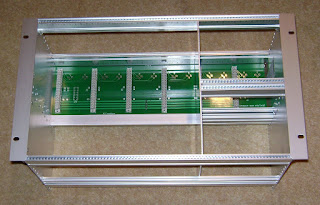
The sub-rack arrived today from SRS so I have spent the evening assembling it.  SRS sent the basic rack already assembled which saved me a lot of work.


As this is a four channel mixer, I needed to divide the rack into one space of 4 channels each 6U high and another space two channels wide but divided into two 3U high spaces. In the top space will go the bus amplifiers and in the bottom space will go the monitor section of the mixer. Here is the SRS divider kit:


And fitted to the basic rack.


 You can clearly see the divider towards the right and the two 3U high spaces it provides.  Next I added the EZ Tube Mixer backplane PCB:


Notice haw both 6U and 3U modules can plug into the one backplane. You could also have active modules in the lower 3U space if desired. Rather than have another backplane PCB spanning the whole width of the mixer just for two modules, SRS do a converter kit that allows you to fit a pair of regular 32 way connectors direct to the rails. One of these modules could be a headphones amplifier made from a standard EZTubeMixer Eurochannel V3 card where the output stage current has been increased. The other could perhaps be an opto conpressor. For now it is just going to be a simple monitor section.

SRS also provided top and bottom screens but I will not fit them until I have finished wiring the monitor section as access will be easier. I then placed a prototype module and some drilled panels to get a feel for the completed unit:


And lastly tried the rack in the mixer enclosure:


Note the 2U space below the sub-rack. I will fit a standard 2U panel in here and fit later the rotary faders to it.

Sunday 3 February 2013

Drilling Front Panels


After centre punching, the panels are drilled. A pillar drill is essential for this; it is well worth the investment. It is also well worth investing in a good set of drill bits. The slot for the push buttons (top left) is drilled as a rough series of holes and then filed by hand.


Monday 28 January 2013

Making Front Panels


I have now finalised the position of all the controls on both the Pultec and Helios type channels. The next step is to drill all the holes in the blank panels. To do this I print off copies of the front panels from Front Panel Designer with the 'Print Reference Points' option selected. This prints the panel with the centres of all the holes marked by a small red cross. I then carefully cut out the prints of the panels and glue them to the blank aluminium panels using diluted PVA. When that has been done I centre punch every hole ready for drilling. It does not matter if the paper legend gets damaged during drilling as it will be removed after drilling and replaced with a vinyl one. The picture below shows the four channel panels with their stuck on paper legends after centre punching.


Friday 25 January 2013

Channel Front Panels


I have been trying to finalise the layouts of the front panels of the two different types of channel. I use Front Panel Designer for this. When the layout looks good I print it out and place the knobs on it to get a better feel for the overall appearance. Here is a picture of one I finished this evening. It is the Helios 69 style channel.


For prototyping purposes I print a version of the front panel layout with the centres of each hole marked. I then glue this to a blank front panel and use it as a template for drilling the holes. After removing the paper layout I print out another one in colour on sticky backed vinyl and carefully apply it to the metalwork.

The legend has gone through a number of revisions but I think I have now settled on a standard for character sizes and font. Section headings, like HIGH in the above picture, are 3.5mm high whilst elements within a section like the frequencies on an EQ switch or the labels for individual pots are 2.5mm high. The font used in all cases is DIN17, 1-stroke as defined by Front Panel Designer. Here is a picture of the Pultec channel. As you can see I have not yet finalised knobs. The larger knobs for the frequency selection and mic gain I have selected because they push on to the D shaped shaft of the quarter inch Grayhill switches used. You don't have to worry about getting the pointer lined up correctly with the legend because these knobs have removable caps so you can rotate the cap to the right position and glue it in place.


All the pots have splined shafts and take push on knobs. Again the exact orientation of the pot does not matter as you can simply set the pot fully anti-clockwise and push on the knob at the appropriate orientation. I think so far my favourite small knobs are the bottom right hand three in the above picure.

Sunday 13 January 2013

EZTubeMixer Demo Mixer

The purpose of this blog is to document the building of a 4 channel all vacuum tube demonstration mixer intended to showcase all the key elements of my EZTubeMixer design that can be found at:

groupdiy.com

The design caters for three alternative microphone transformers by Sowter, Jensen and Cinemag, The mixer will be built with two channels using Sowter transformers and one each using the Cinemag and Jensen types. The design also supports a 3 band Pultec style EQ or one modelled on the Helios Type 69. Two channels with have the Pultec EQ and the other two will have the Helios EQ.

Each channel will have:


  • Switches for phantom power, phase, 20dB pad and mic/line selection
  • 12 position stepped gain control covering a gain range from 60dB downwards in 3dB steps
  • Smart Pan (pan control only selected when both left and right buses are selected)
  • AUX send switchable pre or post fader
  • Pultec or Helios 3 band EQ with EQ in/out switch
  • Rotary channel fader
  • Direct out


Channel PCBs fit into a 6U high 14HP wide standard Eurocard slot.


Six channels will fit across a standard 19 inch sub-rack. In this mixer four channels are used for inputs and the other two for the master section. The sub-rack is fitted with a backplane into which the channel PCBs are plugged using a 32 way 0.2inch pitch connector.


The master section will contain:


  • Master rotary fader
  • Master AUX send fader
  • AUX return with Smart Pan
  • Monitor selection and level control
  • VU meters


The mixer will be housed in an off the shelf enclosure made by Rackz

They make a very nice sloping 19 inch rack enclosure with an add-on meter bridge.


You can see where the two VU meters have been mounted in the bridge. A standard 6U high sub-rack which which house the channels and master section is fitted into the sloping front panel of the Rackz enclosure. The sloping area is 8U high which leaves a 2U space below the channels sub-rack for rotary faders and a scribble strip.

The picture above does not really show the sloping front so here is one that does!


I just ordered the sub-rack that will house the channel modules. I ordered this from SRS in the UK because, although sub-racks are available at similar prices from distributors, you cannot buy all the little bits and pieces needed to customise the sub-rack. With SRS you just phone up, tell them what you want and they email you a quote. In this case I have four channel modules each 6U high and 28HP wide which together use up two thirds of the width of the sub-rack. In the remaining third I want to have the mix amps, AUX send masters, AUX returns and monitor selection and level controls. The mix amps and AUX sends only need to be 3U high so I want to put them at the top of the remaining third so they plug into the backplane. Below these I want to have a panel containing the monitor section. So I need a little bit of mechanical wizardry that divides the 6U high space into two 3U high spaces and that's where SRS really comes into its own - their guys know just what parts you need to do this. I also want to fully screen the sub rack so I need top and bottom  vented screens and again SRS know what I need. Their MOQ is only 100GBP which a custom sub-rack like this easily exceeds so you get just what you need with no penalties for being a small order. Check them out srs-products.co.uk